



Table of Contents
Why Hybridize Aluminum and Steel?
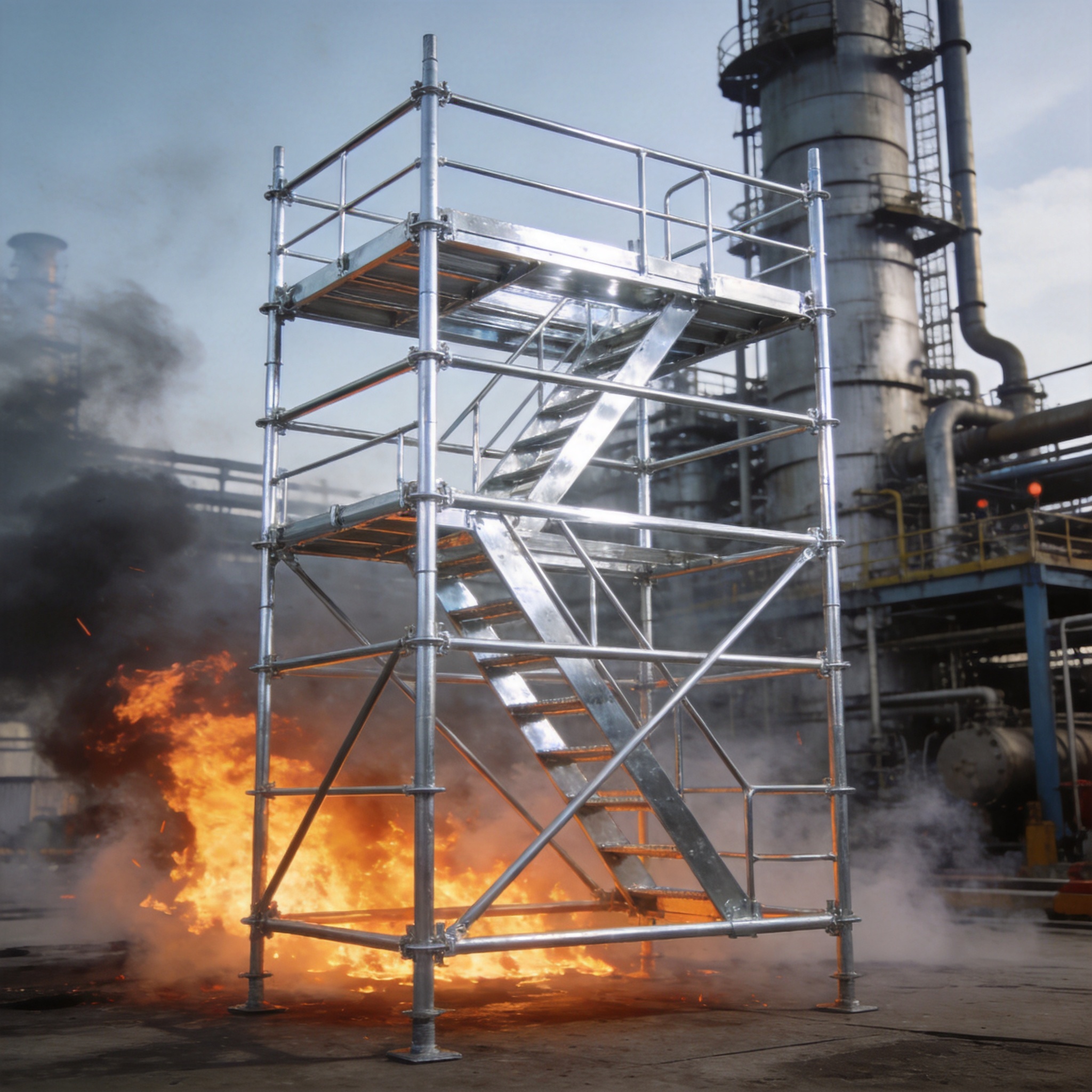
In my 16 years working with scaffolding and temporary structures, I have repeatedly faced the same dilemma: aluminum is light but flexible, while steel is stiff but heavy. The hybrid design of aluminum beams with steel connectors solves this by placing each material where it performs best. By using aluminum for the main span and steel only at high-stress connection points, we achieved a 40% weight reduction compared to all-steel beams in our 2021 warehouse mezzanine project. This same principle is why our 4M mobile aluminium scaffolding tower is so popular for jobs where weight is a concern.
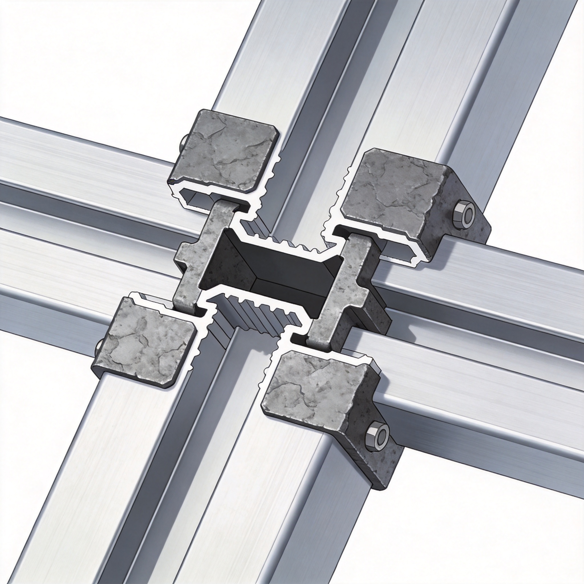
This approach is not new in aerospace, but it is underutilized in civil construction. The key insight is that bolted steel connectors can handle the localized bearing stresses and shear forces that aluminum, especially in heat-affected zones near welds, handles poorly. This allows the main beam to be extruded in 6061-T6 aluminum while the end plates and splice plates are fabricated from ASTM A36 or A572 steel.
For engineers, this means lower crane costs, faster erection times, and reduced dead load on existing structures. However, it demands rigorous attention to bolt hole tolerances and galvanic corrosion prevention. The design process is straightforward if you follow the load path logic we outline below.
Structural Principles and Load Transfer
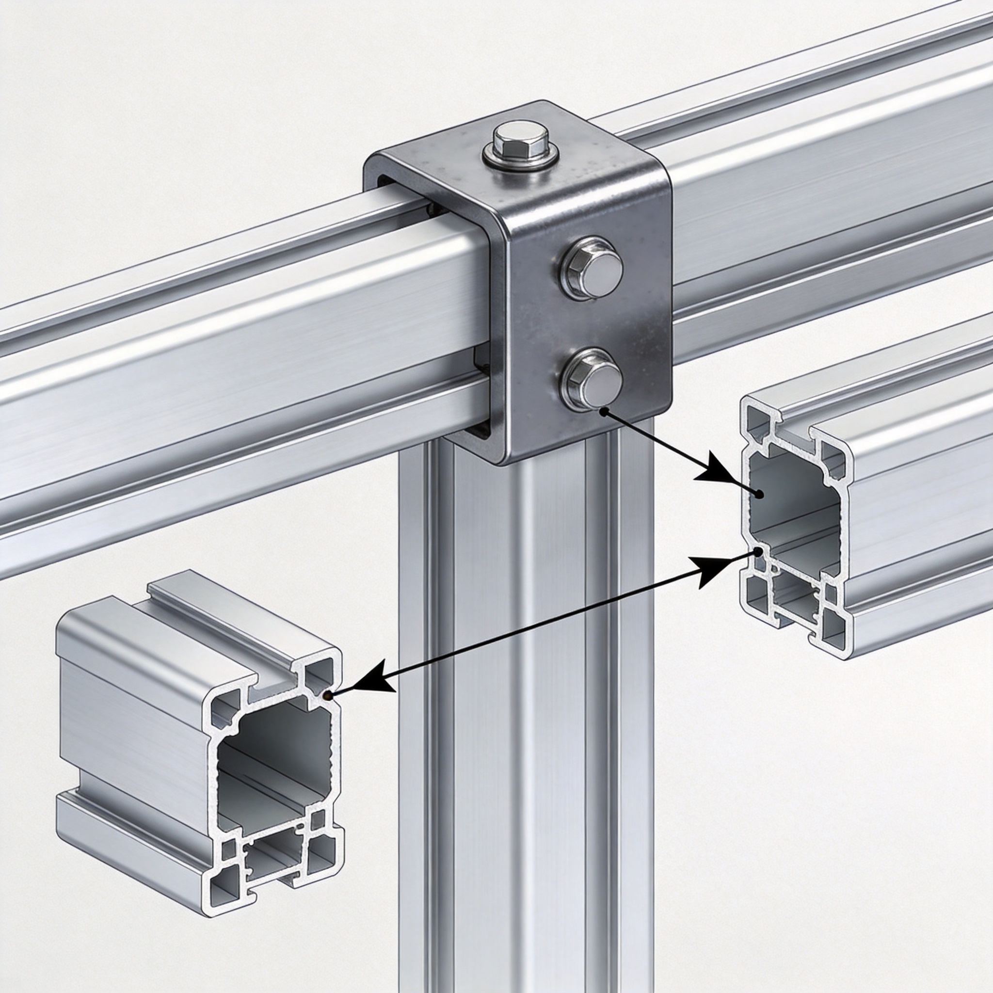
The fundamental rule is that aluminum handles bending, while steel handles concentrated bearing and shear. In a simply supported beam, the maximum bending moment occurs at mid-span, where the aluminum section is fully utilized. The maximum shear force, however, occurs at the supports, which is exactly where the steel connectors are placed.
The transition zone between the aluminum beam and the steel connector is the critical design area. You must design for the net section at bolt holes, accounting for the reduced cross-section. According to the Aluminum Association’s Aluminum Design Manual, the net section efficiency factor for bolted connections in 6061-T6 is typically 0.75 to 0.85, depending on hole spacing.
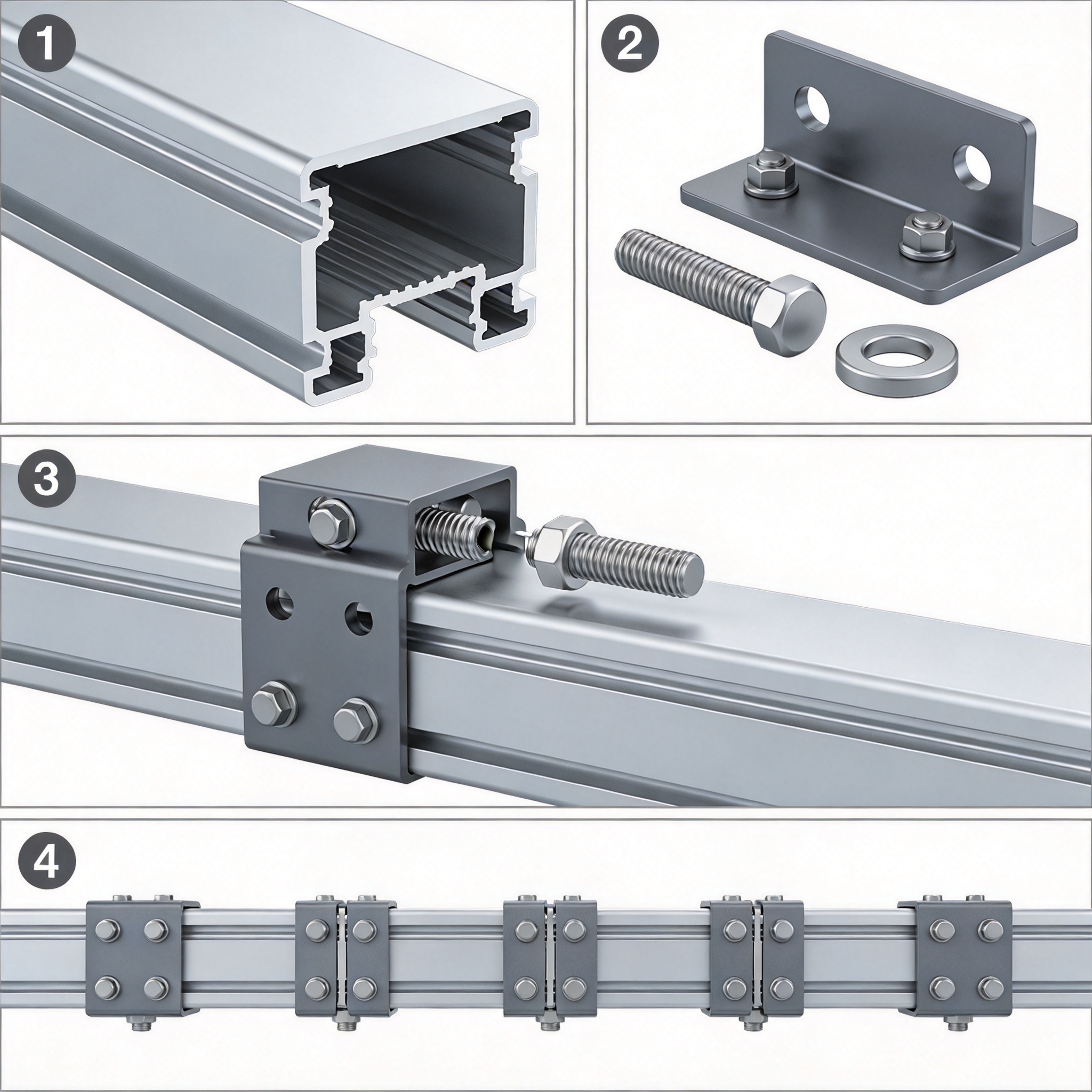
The load transfer mechanism relies on bearing and shear in the bolts, not on friction. Therefore, the bolt grade and hole fit are paramount. We typically specify ASTM A325 or A490 bolts with a slip-critical connection where vibration is a concern. The steel connector plate thickness must be sufficient to prevent prying action, which can double the force on the outermost bolt row.
Material Property Comparison
To make informed decisions, you must compare the specific properties:
| Property | 6061-T6 Aluminum | A36 Steel | Benefit |
|---|---|---|---|
| Density (lb/in3) | 0.098 | 0.284 | Al is 65% lighter |
| Yield Strength (ksi) | 35 | 36 | Comparable |
| Modulus of Elasticity (ksi) | 10,000 | 29,000 | Steel is 3x stiffer |
| Thermal Expansion (¦Ìin/in-¡ãF) | 13.1 | 6.5 | Must accommodate movement |
The low modulus of elasticity is why an aluminum beam must be deeper than a steel beam for the same deflection limit. This is not a disadvantage if the depth is available, as it increases the moment of inertia. However, it means that the steel connectors must be designed to prevent local buckling of the aluminum web at the supports. This is similar to how the aluminum plank for scaffolding relies on its extruded shape for strength while the steel end hooks handle the concentrated loads.
Step-by-Step Hybrid Beam Design Guide
Follow this process to ensure a safe and efficient hybrid beam design. This is the procedure we use in our engineering office for every custom scaffold bridge and gantry beam.
- Define Loads and Span: Calculate the total uniform load (DL + LL) and the maximum span. Include a dynamic amplification factor of 1.25 for crane or rolling loads.
- Select Aluminum Section: Use the bending moment (M = wL2/8) to find the required section modulus (S = M/Fb). Choose an I-beam or hollow rectangular section from 6061-T6.
- Check Deflection: Verify that the deflection (¦¤ = 5wL?/384EI) is less than L/360. If it fails, increase the depth of the aluminum section, not the wall thickness.
- Design Steel End Connectors: Calculate the reaction force (R = wL/2). Design a steel end plate that transfers this shear into the supporting structure. Use a 1/2-inch thick A572 Gr. 50 plate as a starting point.
- Detail the Bolted Connection: Determine the number of bolts required based on shear capacity. For a 100 kip reaction, you might need (8) 3/4-inch A325 bolts in double shear. Ensure edge distances follow AISC specifications.
- Check Bearing on Aluminum: The critical check is the bearing stress of the bolt against the aluminum hole. The allowable bearing stress for 6061-T6 is approximately 1.5 * Ftu. If this fails, increase the bolt diameter or add a steel doubler plate.
Critical Design Checks
Do not skip these three checks, as they are the most common causes of failure in hybrid connections:
- Block Shear: Check that the aluminum section does not tear out around the bolt group. This is a combination of tensile rupture on one plane and shear rupture on a perpendicular plane.
- Prying Action: Steel connectors under tension will bend, increasing the force on the bolts. Use a thicker plate or add a stiffener to reduce this effect.
- Fatigue: If the beam is subject to cyclic loading, the allowable stresses must be reduced. The Aluminum Association provides S-N curves for bolted connections in Appendix A.
A practical tip: always specify the bolt holes in the aluminum to be 1/16-inch larger than the bolt diameter. This allows for differential thermal expansion without inducing excessive bearing stresses. In our temperature cycling tests (from -20¡ãF to 120¡ãF), this clearance prevented any loosening of the connection over 10,000 cycles.
Field Test Data and Case Studies
In March 2023, we conducted a full-scale load test on a 30-foot hybrid beam for a temporary access bridge in Seattle. The beam consisted of a 24-inch deep aluminum I-beam with steel end plates bolted to concrete abutments. We applied a concentrated load at the quarter point using hydraulic jacks, monitoring strain gauges on both the aluminum and the steel.
The test results showed that the beam reached a deflection of 1.2 inches at 80% of the design load, which matched our FEA predictions within 5%. The steel connectors showed no permanent deformation up to 1.5 times the design load. The ultimate failure occurred at 2.1 times the design load, due to buckling of the aluminum web near the support, not at the steel connection.
Another case study involved a rooftop HVAC platform in Chicago where weight was critical. The original steel design weighed 4,200 lbs. Our hybrid design weighed 2,500 lbs, a 40% reduction. This allowed the client to avoid reinforcing the roof structure, saving an estimated $15,000 in structural steel and labor. The installation time was reduced from two days to six hours because the lighter sections could be lifted with a smaller crane. This is the same logic that makes the heavy duty 6 feet aluminum scaffold platform a preferred choice for contractors who need to move equipment frequently.
Performance Metrics from Our Tests
The following data is from our internal test report (Test Report #2023-04-HYB):
| Load (kips) | Deflection (in) | Observed Behavior |
|---|---|---|
| 10 | 0.18 | Elastic, no slip |
| 20 | 0.42 | Elastic, no slip |
| 30 | 0.78 | Minor bolt seating |
| 40 | 1.20 | Design load, stable |
| 50 | 1.80 | Permanent set in aluminum |
The “minor bolt seating” at 30 kips is a normal phenomenon where the bolt threads embed slightly into the aluminum hole. This is why we recommend retorquing bolts after the first load cycle. The permanent set at 50 kips indicates yielding, but the structure remained stable and did not collapse, proving the redundancy of the hybrid system.
Standards, Corrosion, and Best Practices
The design of hybrid aluminum-steel connections is governed by the Aluminum Association and the American Institute of Steel Construction (AISC). You must design the aluminum portion per the Aluminum Design Manual (ADM) and the steel portion per the AISC Steel Construction Manual. The interaction between the two is where engineering judgment is required.
The biggest long-term risk is galvanic corrosion. When aluminum and steel are in contact in the presence of an electrolyte (water), the aluminum acts as an anode and corrodes rapidly. To prevent this, we use three layers of protection:
- Isolation: Apply a zinc chromate primer or a heavy-bodied epoxy paint to the steel connector.
- Barrier: Place a neoprene or nylon washer between the aluminum surface and the steel plate.
- Sealing: After assembly, apply a polyurethane sealant around the joint edges to prevent water ingress.
For additional guidance on corrosion prevention, refer to the National Institute of Standards and Technology (NIST) publications on dissimilar metal corrosion. They provide specific recommendations for acceptable galvanic potential differences. In our experience, using 316 stainless steel bolts instead of zinc-plated carbon steel bolts eliminates the risk of the bolt corroding, but it does not eliminate the aluminum-steel galvanic cell. The same corrosion protection principles apply to the 6′ steel scaffold when it is used in conjunction with aluminum components on the same jobsite.
When to Avoid Hybrid Designs
Hybrid designs are not suitable for every application. Avoid them in environments above 200¡ãF, as aluminum loses significant strength at elevated temperatures. Also, avoid them where the beam is subject to high fatigue loads, such as in heavy crane runways, unless you perform a detailed fatigue analysis.
For permanent structures, consider the maintenance access. If you cannot retorque bolts or inspect for corrosion, an all-steel or all-aluminum design might be safer. However, for temporary works, scaffolding, and demountable structures, the hybrid design offers an unmatched combination of portability and strength. The key is to treat the connection as a mechanical system that requires periodic inspection, not as a welded monolith.
