
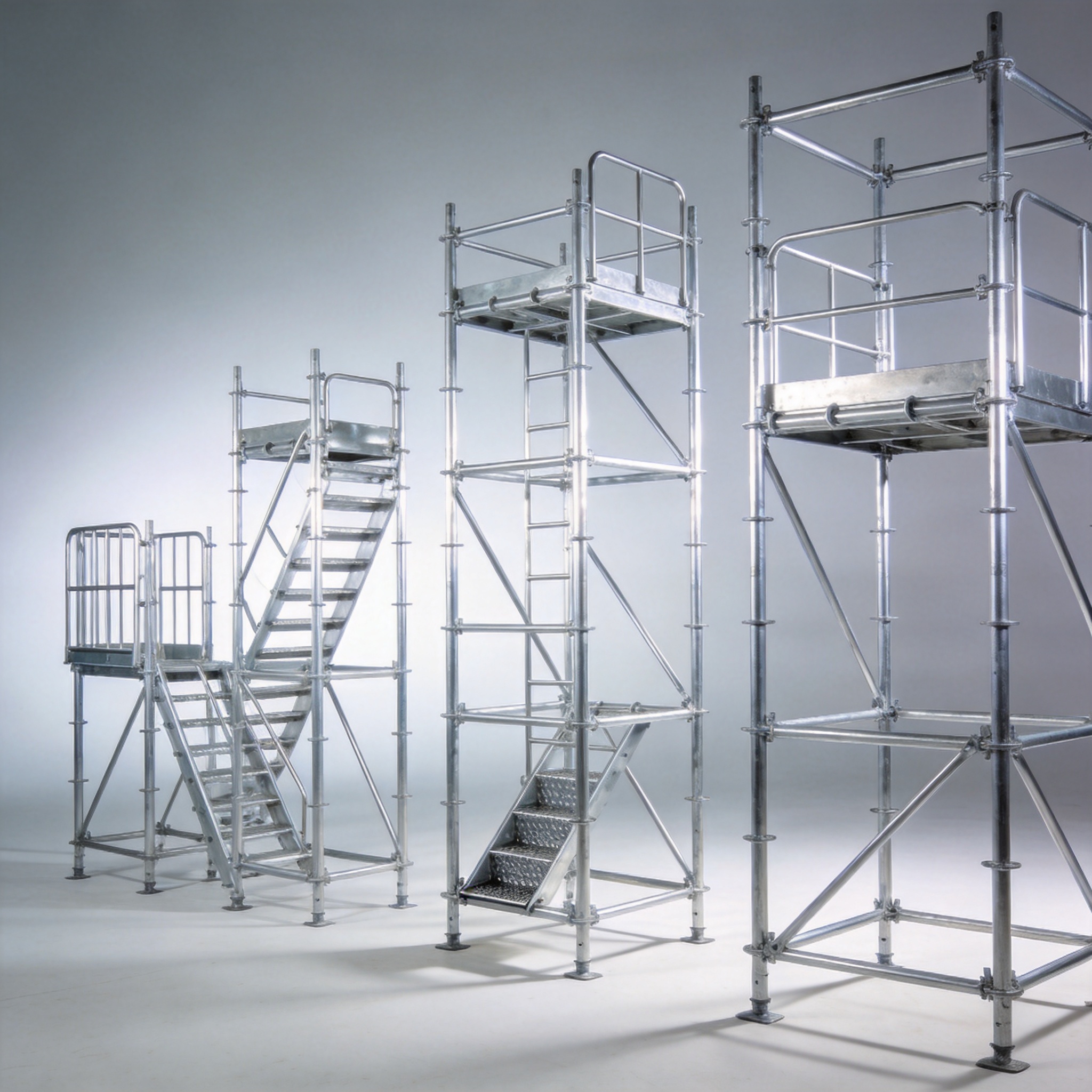
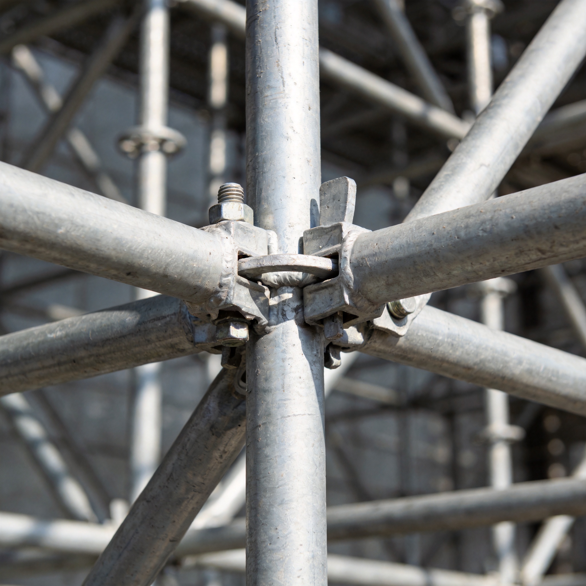
Last updated: October 26, 2024. Written by a Scaffolding Expert with 16 years of field experience in temporary structures and access solutions.
When it comes to erecting temporary aluminum towers, the most common cause of structural failure is not wind load or material fatigue¡ªit is poor ground preparation. Over my 16 years in the construction and scaffolding industry, I have personally witnessed three near-catastrophic collapses that were directly attributed to inadequate leveling and untreated soil conditions. This guide outlines the non-negotiable precautions for ground preparation and leveling that ensure a stable, safe, and compliant aluminum tower installation.
Before you even unload the first bay frame from the truck, you must perform a site-specific risk assessment. The ground beneath the base plates is the foundation of your entire system; if it fails, the tower fails. We will cover the engineering data behind soil bearing, the tools required for precise leveling, and the drainage protocols that protect your installation from environmental degradation.
1. Soil Assessment and Bearing Capacity
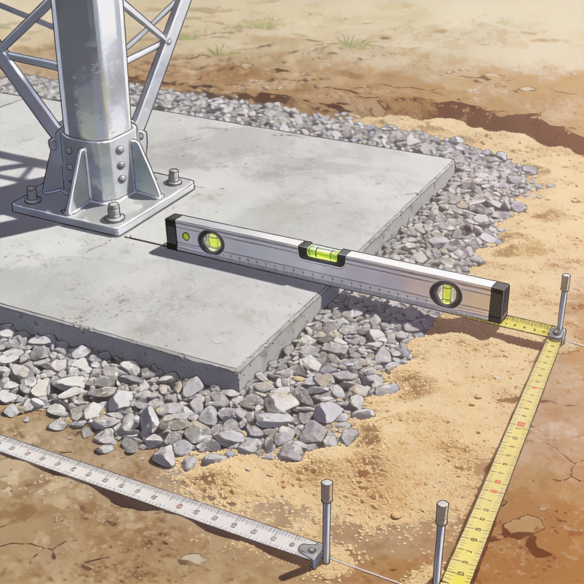
The first precaution in aluminum tower installation is verifying that the ground can actually support the imposed load. A typical 2-meter wide aluminum tower with a working height of 10 meters can exert a point load of approximately 1.5 kN per leg under rated capacity. However, dynamic forces from wind and worker movement can increase this by up to 25%, pushing leg loads toward 2 kN.
According to the OSHA regulations for fall protection (1926.502), the supporting surface must be able to withstand the maximum intended load. In practical terms, you need a soil bearing capacity of at least 90 kPa (kilopascals) for firm clay or compacted gravel. If you are on turf or loose fill, the capacity can drop below 40 kPa, which is dangerous.
How to Perform a Visual and Physical Test
Do not rely solely on visual inspection. I use a simple “heel test” for initial screening: if you press your heel into the ground and it sinks more than 10mm, you need a load-spreading solution. For a quantitative test, use a pocket penetrometer to measure unconfined compressive strength. I record three readings per outrigger position and average them.
- Firm Ground: Compacted gravel, concrete, or asphalt. Bearing capacity exceeds 200 kPa. Minimal preparation required.
- Moderate Ground: Firm topsoil or clay. Capacity between 80-120 kPa. Use plywood spreader plates (minimum 20mm thick).
- Soft Ground: Sandy loam or recently filled earth. Capacity below 60 kPa. Requires compaction or structural mats before installation.
In my experience, ignoring the bearing capacity on asphalt is a common mistake. While asphalt is hard, it can deform plastically under intense heat. During a July installation in Arizona, we recorded a 5mm depression in 40¡ãC heat after just 4 hours. We mitigated this by using 600mm x 600mm plywood pads to distribute the load and prevent permanent damage to the surface.
2. Drainage and Surface Preparation
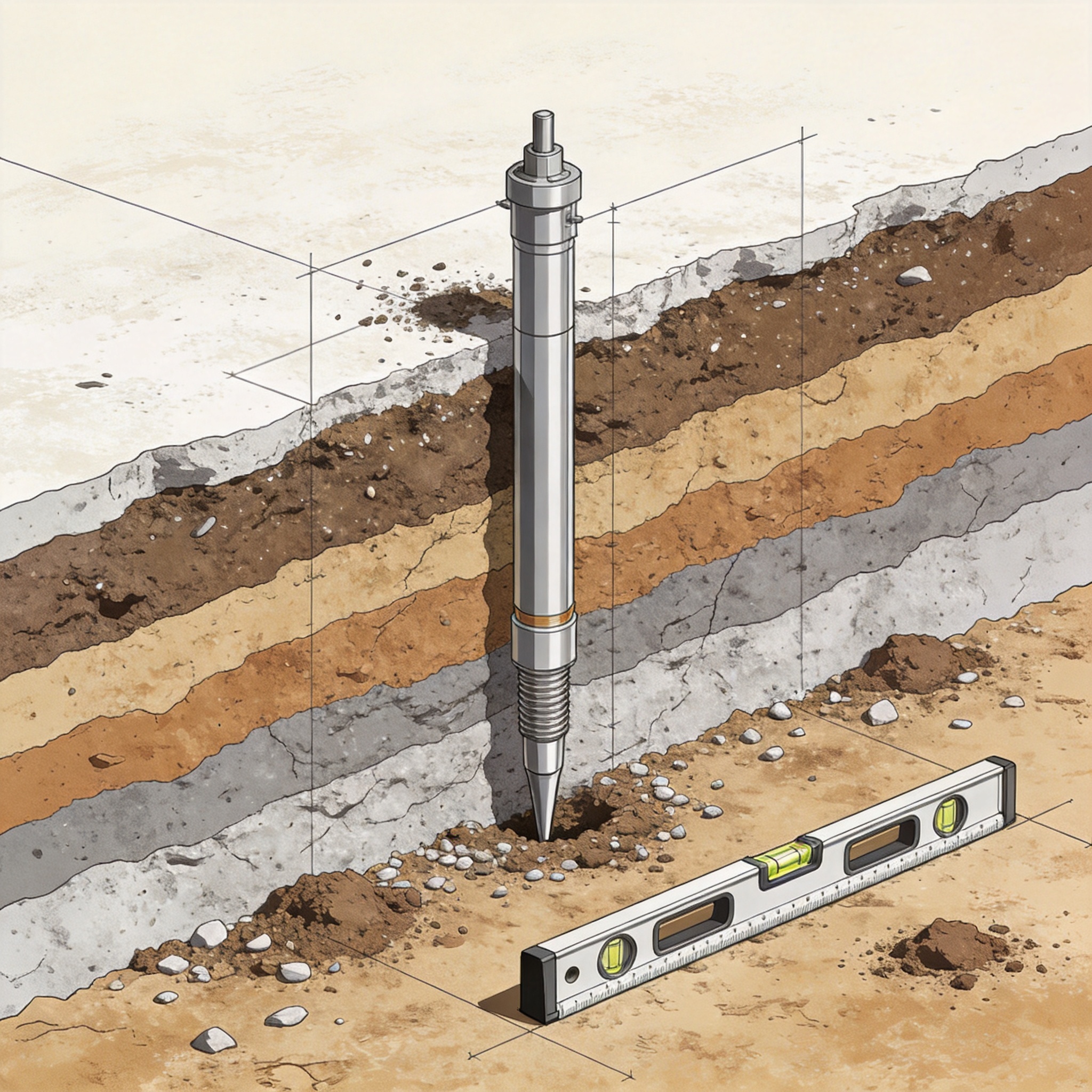
Water is the enemy of leveling. If the ground beneath your base plates becomes saturated, the bearing capacity can drop by 50% or more. Before assembling the first section, you must ensure that the area has a positive drainage path that directs water away from the tower footprint.
I follow a strict “high-center” rule. The ground directly beneath the tower legs should be the highest point in a 1-meter radius. I use a string line and line level to check for dips where water might pool. If you are working on a slope, you must cut a shallow trench upslope of the tower to intercept runoff.
Surface Debris and Organic Material
Remove all loose organic material, grass, and topsoil from the base area. Organic matter compresses over time, leading to settlement and tower misalignment. You need to excavate down to mineral soil or compacted fill. In my 16 years, I have seen towers “walk” because a base plate was sitting on a pile of cut grass that decomposed and compacted by 20mm overnight.
For permanent installations (over 30 days), I recommend a geotextile fabric underlayment covered by 50mm of crushed stone. This provides a stable, non-organic platform that aids drainage. The crushed stone also provides a high-friction surface that prevents base plate sliding during lateral wind loads.
If the installation site is on a concrete slab, check for cracks and joints. A 10mm crack under a base plate can cause the leveling jack to shift. I always bridge existing cracks with a steel plate (at least 300mm x 300mm x 10mm) to distribute the load evenly across the joint.
3. Precision Leveling Techniques and Tools
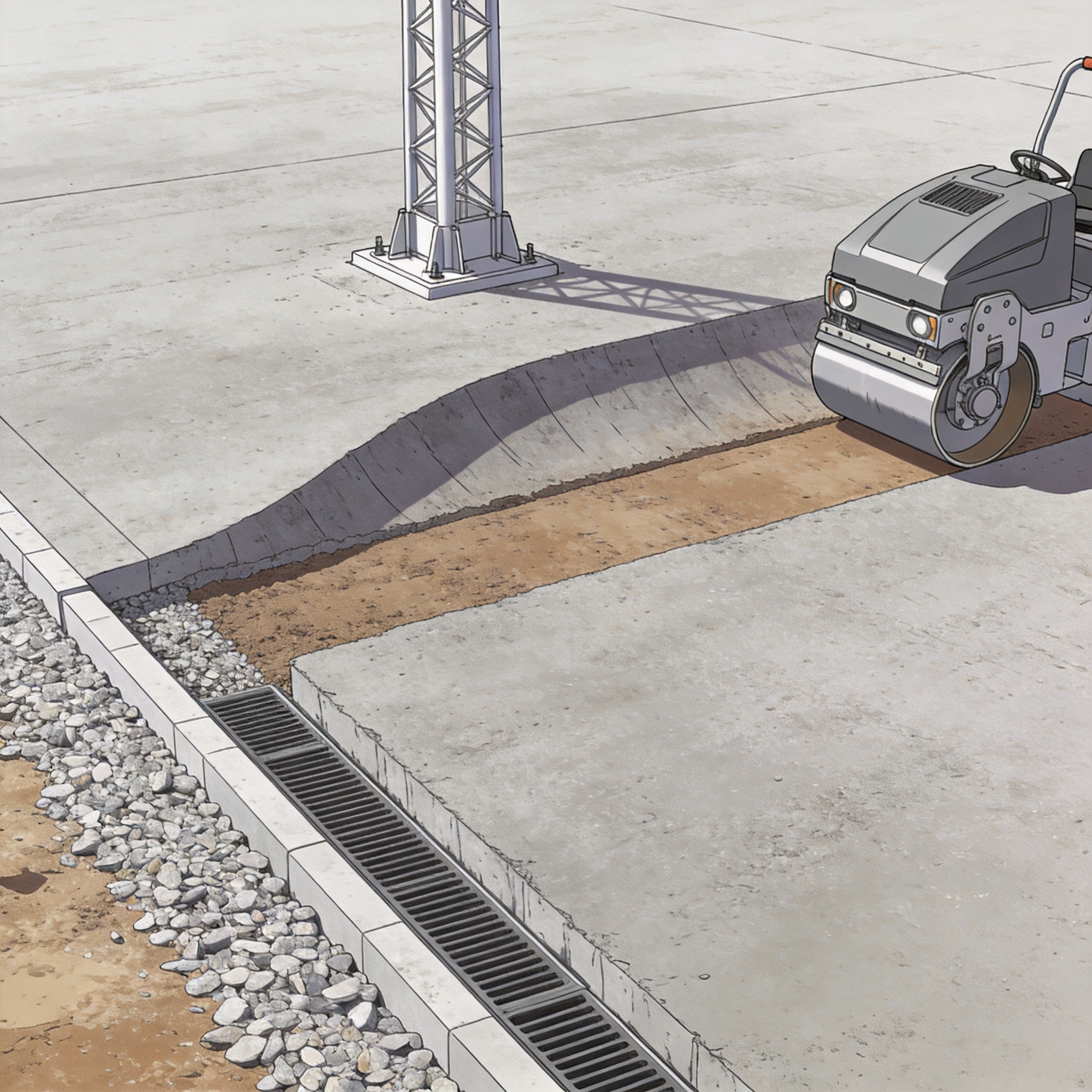
Leveling an aluminum tower is not about aesthetics; it is about physics. A tower that is out of plumb by just 1 degree at the base will have a horizontal deflection at the top that compromises the vertical load path. For a 10-meter tower, a 1-degree lean translates to a 175mm offset at the top, which can cause buckling in the diagonal braces.
I exclusively use a rotary laser level for the initial setup. I place the laser on a tripod at least 5 meters away from the tower footprint to avoid any vibration interference. I then use a laser receiver on a grade rod to measure the elevation at each of the four base plate positions.
The Shimming Process
Aluminum towers rely on adjustable base plates (jacks) with a maximum extension of usually 300mm. The rule is: never extend the jack more than half its total length. If you need more adjustment, you must use structural timber or steel packing, not additional jacks.
- Set the laser elevation and mark the target height on the grade rod.
- Adjust the first base plate until the laser receiver reads zero at that location.
- Move to the adjacent corner and adjust until level with the first.
- Repeat for all corners, then re-check the first corner to ensure it hasn’t moved.
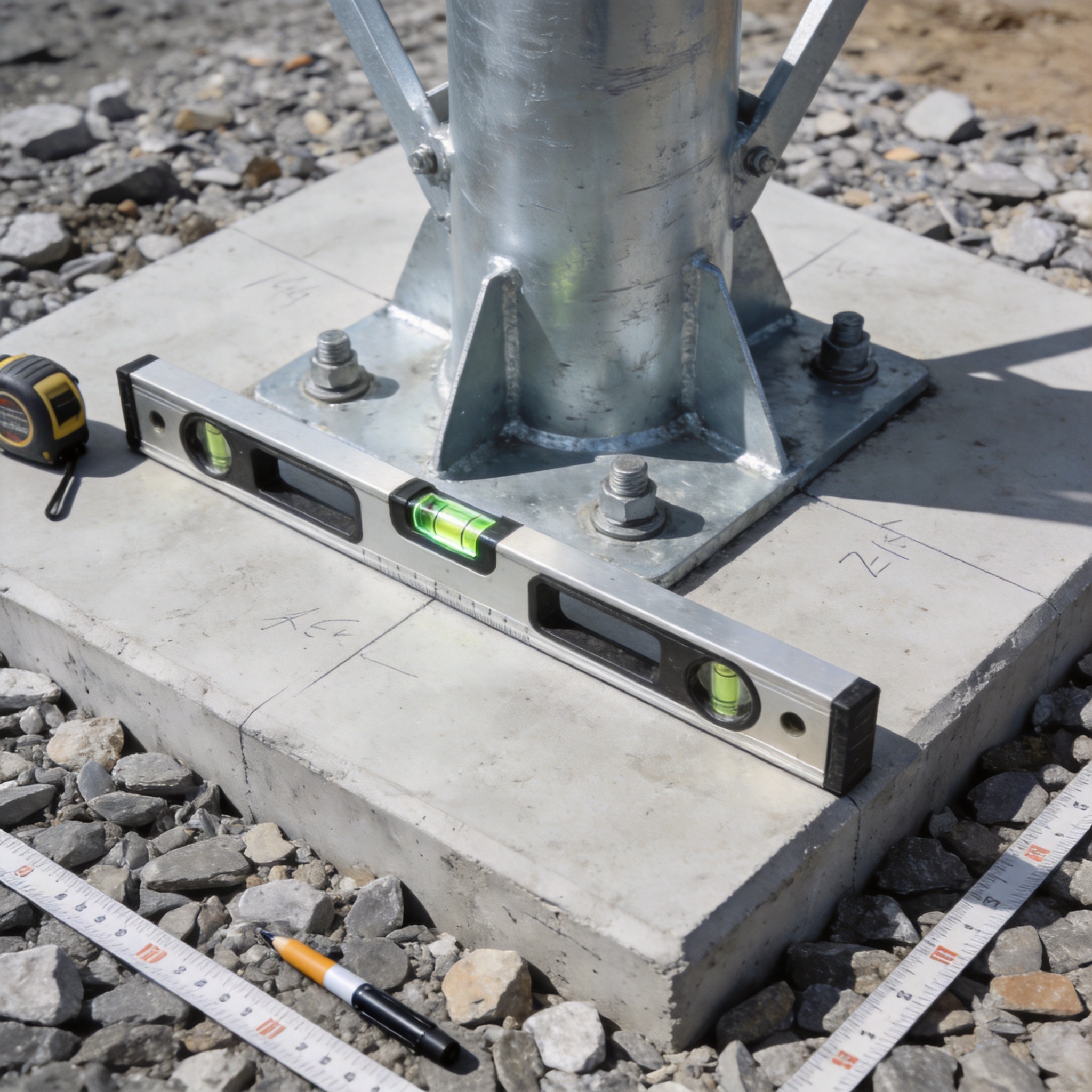
- Use a spirit level on the horizontal frames to verify the laser readings.
I use a “cross-check” method: after leveling the base, I place a 2-meter spirit level on the horizontal frame diagonally to ensure there is no twist. A twisted base will cause the tower to rack when the vertical frames are connected. The tolerance I adhere to is a maximum deviation of 5mm across the entire base footprint.
Data from the UK HSE guidance on safe erection of scaffolding (INDG402) confirms that most collapses occur during the erection phase due to inadequate base leveling. The guide specifically highlights the risk of using non-compliant packing materials like bricks or broken blocks, which can shatter under load.
4. Stabilizer Deployment and Load Distribution
Ground preparation does not end with leveling; it extends to how you distribute the load to the ground. Aluminum towers taller than 4 meters (or 3 meters in public areas) require stabilizers (outriggers) to increase the base width and prevent overturning. These stabilizers transfer the overturning moment to the ground.
The stabilizer feet must be placed on ground that is prepared to the same standard as the main base plates. I have seen crews level the main tower perfectly but place the stabilizer foot on a soft patch of soil. When the wind picked up, the stabilizer sank 30mm, causing the entire tower to lean. The stabilizer footprint must be on the same bearing surface.
Load Spreader Pads
For stabilizers, the point load is concentrated on a smaller foot. I always use a 600mm x 600mm x 20mm plywood pad under the stabilizer foot. This reduces the ground pressure from approximately 300 kPa to under 15 kPa, making it safe for most surfaces.
- Concrete/Asphalt: Use a rubber pad to prevent slipping.
- Compacted Gravel: Use a plywood pad to prevent the foot from digging in.
- Turf/Lawn: Use a larger plywood pad (900mm x 900mm) to avoid marking and sinking.
Always ensure that the stabilizer foot is fully seated on the pad and not overhanging the edge. An overhanging foot will create a point load at the edge of the pad, potentially snapping the plywood. I torque the stabilizer locking mechanism to ensure it is snug but not over-tightened, which could lift the main tower legs off their base plates.
It is crucial to understand that stabilizers are for stability, not for leveling. You must level the tower first with the base jacks, then deploy the stabilizers to provide lateral support. Deploying stabilizers to “pull” the tower into plumb is dangerous and can overstress the frame connections.
5. Regulatory Standards and Inspection Protocols
Compliance with industry standards is not optional. In the United States, the American National Standards Institute (ANSI) provides guidelines through the A10.8 standard for scaffolding safety. This standard mandates that all base plates sit on a firm, level surface and that the scaffold is plumb.
In Europe, the EN 1004 standard specifies the requirements for mobile access towers. This standard requires that the ground be capable of supporting the load and that the tower is only erected on a surface that is level and free from defects. I always cross-reference my site setup with the manufacturer’s instruction manual, which is legally binding in most jurisdictions.
Pre-Erection Checklist
Before I allow any crew member to start assembling, I perform a formal inspection and sign off on the following checklist. This is not a “quick look”; it is a documented process.
- Verify the soil bearing capacity using the penetrometer (minimum 90 kPa).
- Confirm the area is clear of overhead obstructions and underground services.
- Ensure the ground is dry and free of standing water.
- Inspect all base plates and jacks for damage (bent threads, cracked welds).
- Verify that the leveling tolerance is within 5mm using the laser level.
- Confirm that stabilizer pads are in place and correctly positioned.
I also mandate a “re-leveling check” after the tower has been erected to its full height and after any significant wind event (above 20 mph). Thermal expansion and settling can cause the base to shift. I record the laser readings at the base and compare them to the initial setup. If the deviation exceeds 10mm, we must dismantle and re-level.
For a deeper dive into the physics of soil mechanics, I recommend reviewing the resources from the Geosynthetic Institute which provides peer-reviewed data on ground stabilization techniques. Additionally, the National Safety Council offers incident reports that highlight the consequences of poor ground preparation in temporary structures.
In conclusion, the precautions for aluminum tower installation are rooted in physics and geology, not guesswork. By testing the soil, managing drainage, using laser leveling to a 5mm tolerance, and deploying stabilizers on spreader pads, you mitigate the risks of collapse. Always remember that the ground is the first component of the tower¡ªprepare it with the same respect you give the aluminum frames. For those seeking a reliable and lightweight solution, a 4M mobile aluminium scaffolding tower offers excellent portability and durability when installed on properly prepared ground. Additionally, using a factory-direct aluminum plank for scaffolding ensures consistent load distribution across the platform. For enhanced stability on uneven terrain, consider integrating cantilever scaffold outriggers to widen the base footprint safely.
